


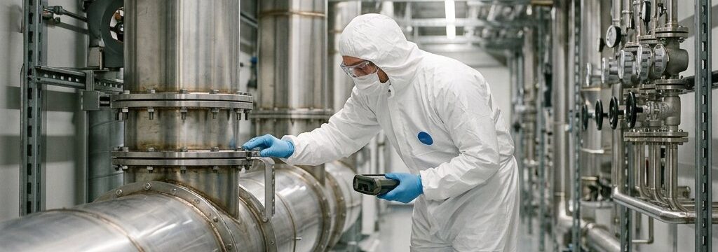
Process Exhaust in Semiconductor Cleanrooms

Process exhaust in semiconductor cleanrooms is about far more than extracting “dirty air”. It involves a set of gas streams from different tools and process steps, each with its own chemical composition, temperature, moisture load and failure behaviour. Treating those streams too early as one uniform exhaust demand increases the risk of contamination, corrosion, deposits, unstable flow and unclear safety margins.
Table of Contents
- 1Where process exhaust arises and why one generic approach does not work
- 2Which exhaust streams you need to assess separately
- 3Which design data your team needs in advance
- 4Where moisture, particles and condensation cause problems
- 5How to align controls and safety functions properly
- 6What you need to demonstrate during FAT, SAT and commissioning
- 7How maintenance, pressure drop and fan capacity influence the design
- 8How to secure process exhaust in the cleanroom design and during later changes
- Show more...
Key takeaways
- Define process exhaust early and treat streams by source and operating mode; avoid generic shared headers.
- Base routing, materials, abatement and monitoring on complete, traceable source data, including peaks and edge cases.
- Segregate streams by chemistry and risk; manage temperature, condensation and particles to prevent fouling and instability.
- Specify clear controls, interlocks, alarms and acceptance criteria across the full operating envelope; verify at FAT/SAT/commissioning and link to recovery-time tests.
- Design for maintainability and pressure-drop margins; manage changes via a URS, explicit triggers and a single source of truth.
The biggest design risks are often not at the nominal operating point, but in edge cases: short peaks, chamber cleans, recipe changes, downtime, restart and maintenance. That is precisely why process exhaust must be defined early in the cleanroom design in line with the semiconductor cleanroom design criteria, based on source data, segregation choices, safety functions and demonstrable test criteria. Below, you can read which information and design decisions are needed to develop this interface between tool, building services and cleanroom in a technically controlled way.
Where process exhaust arises and why one generic approach does not work
By process exhaust, or process extraction, we mean the removal of gases and vapours that come directly from the semiconductor process. This demand does not arise at one fixed location, nor in one fixed form. A wafer cleaning tool can have a very different exhaust profile from an etch process, a CVD system, an epitaxy tool or a chamber clean cycle. Even within one tool, the load often changes by recipe, product type or maintenance condition.
That is why a single generic exhaust line rarely works well as a design basis. Some streams are mainly corrosive, others mainly toxic or flammable. There are also streams with greenhouse gas components, vapours that can condense downstream, or exhaust flows that carry particles and residues and form deposits in ductwork and equipment. On paper, two sources may have a similar flow rate, but in practice behave completely differently once temperature drops, moisture increases or process conditions shift.
A second pitfall is that teams look only at normal production. In practice, the real design case is often determined by idle conditions, start-up, shutdown, purge steps, recipe changes and maintenance or cleaning cycles. In such situations, concentrations, temperatures and flow patterns can temporarily deviate sharply from the nominal profile. If you do not include these operating modes, you risk a system that works under standard operation in practice, but becomes unstable as soon as the tool departs from its most favourable state.
Which exhaust streams you need to assess separately
The choice between separate ducts and shared headers should not rely only on total flow rate or one broad TVOC value. Source-specific chemistry, peak load, contamination risk and suitability for abatement determine whether streams can be combined safely and in a controlled way.
| Stream type | Typical source examples | Main risks | Design implications for routing, treatment and monitoring |
|---|---|---|---|
| Acid/alkali streams | Wet chemical cleaning, wafer cleaning, rinsing and maintenance steps | Corrosion, heat of reaction if mixed incorrectly, aerosols, condensate and material degradation | Assess material selection, pipe gradient and drainage carefully, prevent incompatible mixing, and align pre-treatment and corrosion resistance with the actual source chemistry |
| Solvent or VOC streams | Coat, develop, strip, cleaning and certain drying processes | Flammability, exposure risk, concentration peaks and overloading of abatement | Assess compatible grouping by source, peak profile and operating mode; choose monitoring and treatment that match the actual vapour load rather than average values alone |
| Toxic gases | Certain etch, deposition and cleaning processes | Health risk, acute release, high sensitivity to failures or loss of abatement | Use clear segregation, availability monitoring, alarms, fault logic and a route that remains controlled even in upset situations |
| Flammable gases | Certain deposition, purge or cleaning steps | Ignition risk, unstable mixtures and risk in the event of loss of flow or incorrect dilution | Assess dedicated routing, interlocks, purge philosophy and monitoring of relevant process conditions; mixing can mask short peaks and unsafe combinations |
| Streams with particles or condensables | CVD, epitaxy, chamber clean and processes with residue formation | Deposits, blockage, white smoke formation, additional pressure drop and incorrect flow measurements | Limit dead zones, assess the temperature profile and inspectability; simple droplet removal is not proof that downstream gas-phase components will remain problem-free |
Which design data your team needs in advance
A robust exhaust design starts with complete and traceable source data. Without that foundation, material selection, duct layout, fan selection and controls are largely assumptions.
- For each tool and each relevant process step, record which source falls within scope, including normal operation, minimum and maximum demand, duty cycle and concurrent operation with other sources.
- Describe the full operating envelope for each stream: minimum, normal and peak flow, plus temperature, moisture, pressure conditions and known contaminants at the source.
- Use substance-specific information from chemical inventories, process data and safety data sheets, so the assessment does not stop at general labels such as “acid” or “VOC”.
- Supplement documentation with measurements where composition, concentration or temperature is not sufficiently certain, especially for existing tools, older systems or changed recipes.
- Make an explicit distinction between measured values and assumptions, including date, source owner and uncertainties, so that all suppliers work from the same starting points.
- Also include non-standard but relevant situations such as purge, maintenance, cleaning cycles, idle, restart and off-spec process conditions that temporarily create a different exhaust profile.
- Link the source data directly to design limits for routing, pre-treatment, abatement, monitoring and alarms, so it remains clear later why choices were made.
Where moisture, particles and condensation cause problems
Moisture, aerosols, particles and condensables are often the silent causes of failures in process exhaust and make reducing particle deposition in wafer production more difficult. On paper, the gas stream may appear manageable, while in the actual route residues form that cause build-up on duct walls, corrosion or measurement deviations. This happens in particular when temperature falls, composition fluctuates or a gas stream temporarily behaves differently from standard production.
Vulnerable points are often in predictable locations: external duct sections, cold zones, low points where moisture or residue collects, sections of duct with little velocity, transitions between different headers and routes that cool down during downtime. Restart is also critical. A duct that stays just warm and clean enough during operation can form condensate during downtime or release deposits as soon as flow returns. This causes blockages, unstable pressure behaviour or sudden flow deviations.
A common misconception is that simple pre-treatment, such as droplet removal or an initial separation step, automatically means everything downstream is safe for the fan, ductwork or abatement. That is not self-evident. Gas-phase components can still condense, react or precipitate further downstream as soon as conditions change. The same applies to fine particles that initially remain entrained, but later deposit on bends, sensors or valve seats.
In practice, you see such problems as rising pressure drop, increasingly frequent cleaning, white smoke formation at discharge points or in abatement, and flow signals that no longer correspond stably to the actual process demand. Such failure patterns rarely point to one defective component; they usually show that source chemistry, temperature profile and maintenance strategy have not been designed in sufficient relation to one another.
How to align controls and safety functions properly
Process exhaust only works reliably when the interface between the tool, the exhaust system, the control of pressure difference and ventilation in cleanrooms and any abatement is set up logically and unambiguously. A tool must not only send a “call for exhaust”; it must also be clear when the correct exhaust branch is actually available, which flow or pressure condition is required as a minimum and which functions are enabled in which order.
This starts with the operating logic. Think about start/stop sequence, permissions for tool operation, the status of valves and fans, and alarms in the event of loss of flow or loss of abatement. For some streams, a warning is sufficient for controlled ramp-down, while other situations require immediate lockout or a safe stop. That response depends on the source, the chemistry and the project agreements, but it must never remain implicit. If the system still has to “show” during commissioning what happens in the event of a failure, the design is not yet finished.
In addition, it must be clear how the system responds to upset situations such as abnormal oxygen or flammability conditions, failure of an abatement step, incorrect valve position or unexpected loss of ventilation capacity. Not only the technology, but also signal ownership is crucial here. Which signals come from the tool? Which are monitored in the facility control system? Who is allowed to trip, who is allowed to reset and under what conditions? Without these agreements, maintenance and failures are precisely when the risk of unpredictable behaviour is greatest.
A practical tool is a fixed signal and responsibility matrix. This records, for each interface, which status, notification, permission and reset is supplied and managed by which party. That makes faults quicker to diagnose and prevents an apparently small software or cabling change from later affecting the functional safety of the overall exhaust system.
What you need to demonstrate during FAT, SAT and commissioning
FAT, SAT and commissioning are only valuable if it is clear in advance what “good operation” actually means. A limited test set in one operating mode does not prove that the exhaust system functions in a controlled way across its full range. Including tests for measuring cleanroom recovery time helps validate air change performance and the exhaust/supply balance that underpin process exhaust sizing.
- Define acceptance criteria in advance for each component and each function: which flows, pressures, temperatures, statuses and alarm limits must be demonstrably achieved.
- Set measurement points at relevant locations, for example at tool connections, branches, headers and, where needed, before and after pre-treatment or abatement.
- Determine under which tool modes the test is representative, including normal operation, peak load, transition states, idle and relevant maintenance or cleaning cycles.
- Verify not only nominal operation, but also sensor calibration, scaling settings, valve positions, fan behaviour and the response of control loops.
- Test alarms, fault messages, trips and reset logic explicitly, including behaviour in the event of loss of flow, loss of abatement and switching between operating modes.
- Assess whether the chosen test set really covers the full exhaust range; a “successful” test in a favourable mode can miss critical boundary conditions entirely.
- Link commissioning to an ongoing monitoring strategy, so that loss of flow, fouling and performance deviations become visible at an early stage later on.
How maintenance, pressure drop and fan capacity influence the design
An exhaust system assessed only at the initial design flow is rarely robust enough for long-term use. In practice, the load shifts due to fouling, maintenance condition, tool changes and changing utilisation. That is why accessibility, inspection and replacement of components must be included from the design stage onward, not only once the first fault occurs.
In practice this means, among other things: safe access to modules, sensors and filters, enough space to isolate or replace components, and a logical layout for calibration and service without unnecessary impact on adjacent cleanroom activities. If a sensor can only be reached via complex shutdown or risky dismantling, maintenance is delayed in practice. This increases the chance that small measurement errors grow into incorrect control actions or missed fault signals.
In addition, the total pressure drop must be calculated realistically over the full route: source connections, ductwork, bends, fittings, pre-treatment and any abatement. That total must match the actual capacity of existing or new fans, including fouling allowance and relevant operating variations. A fan that still meets requirements in a clean start-up situation may have too little margin left for stable flow as pressure drop increases.
Intermittent use requires extra attention. Systems that do not remain continuously at temperature or load can suffer from warm-up behaviour, variable draught and a shifting energy balance, with consequences for temperature stability for wafer metrology. This changes not only the flow, but also the likelihood of condensation and deposition. In a modular or expandable cleanroom concept, it is therefore sensible to reserve technical space, service routes and capacity margins in such a way that inspection and adjustment remain manageable later on.
How to secure process exhaust in the cleanroom design and during later changes
Process exhaust should not only come onto the table at the end of a semiconductor cleanroom project. It should be secured starting in the URS phase, where you define which tools and stream types fall within scope, which explicitly remain out of scope and which assumptions still need to be confirmed. That may sound administrative, but it prevents a common problem: an exhaust design that is inadvertently based on incomplete tool data, old recipes or implicit assumptions from different suppliers.
After that, one traceable source of truth is needed for all relevant data: tool inventory, chemical source data, operating modes, design flows, routing choices, open points and confirmed limits of pre-treatment and abatement. If that information becomes scattered across separate emails, revision drawings and supplier documents, it later becomes almost impossible to assess objectively whether a new tool, an adjusted recipe or a flow change still falls within the original design.
For that reason, make change triggers explicit as well. Think of new chemicals, changed airflow per tool, additional equipment, adjusted routing, changed concurrent operation or a different cleanroom operating strategy. Such changes should not only be assessed from a construction or process perspective, but also for their effect on exhaust segregation, pressure drop, controls, monitoring and maintenance. Only then can you decide on a sound basis whether an existing header remains suitable, or whether reconfiguration, additional abatement or extra validation is needed.
This discipline is essential especially in cleanrooms that may later need to be expanded, relocated or modified modularly. Future-proofing lies not only in extra space or a spare connection, but in the fact that design limits remain traceable. Only then can you test a change quickly and safely against the original design basis instead of having to reconstruct what was intended at the time.
That is why, in semiconductor cleanroom projects, process exhaust is best treated as a fixed design interface between tool layout, technical spaces, air handling and serviceability, including considerations around AMHS integration in semiconductor cleanrooms that impact ceiling space, duct routing and exhaust plenums. Not as a late detailed choice, but as an integral part of Design, Engineer, Build, Care. In turnkey and modular semiconductor projects by Cleanroom Systems International, that link is established early, so that expansion, modification and maintenance do not later clash with hidden constraints in the process exhaust. That makes the system not only workable at handover, but also manageable when the production environment changes.
Frequently asked questions
Related articles
Cleanroom interlock: operation, types and design considerations
A cleanroom interlock prevents…
Material Transfer in Aseptic Cleanrooms
Material and equipment transfe…
Cleanroom smoke study
A smoke study makes airflow vi…
